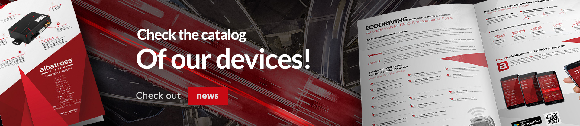
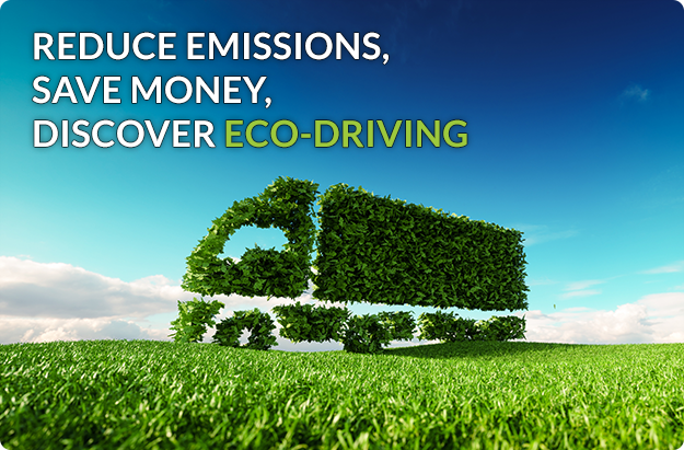
Discover the functionality of our terminals Eco-Driving - saving on the road with Albatross terminals
The Albatross terminals utilize CAN technology to read data from the CAN bus of vehicles. The Advanced Ecodriving Solution leverages various information from the CAN bus and utilizes the mechanisms of a 3D sensor. Ecodriving is an economic and ecological driving technique that significantly reduces operating costs. A driver adhering to ecodriving principles substantially decreases fuel consumption (up to 33%!) and also reduces mechanical wear on vehicle components, especially those related to the braking system and tires. Additionally, the driver contributes to environmental conservation by limiting CO2 emissions and noise pollution. Importantly, there is a reduced risk of accidents through less aggressive, more anticipatory, and prudent driving practices.
CAN technology
The CAN technology utilized in Albatross terminals is responsible for reading information from the CAN bus of the vehicle it is installed in. Based on the retrieved data and applied algorithms, it is easy to determine whether the driver is operating the vehicle economically. The algorithms employed have been developed in collaboration with a professional team specializing in eco-driving training. The CAN bus enables the continuous delivery of real-time data, which enhances the efficiency of the entire system.
3D sensor
The 3D sensor detects events, and then, based on a proprietary calibration algorithm and data analysis, allows for determining the drivers driving style. It protects the vehicle by detecting towing or unauthorized movement of the vehicle.
Data obtained through CAN technology
The total idling fuel consumption
Fuel consumption is calculated when the vehicle speed from the CAN is 0 km/h.
The total driving time
The vehicle driving time is calculated when the engine is running and the vehicle speed from the CAN is greater than 0 km/h.
The total engine idle time
The total engine idle time is calculated when the vehicle speed from the CAN is 0 km/h while the engine is running.
The driving time with the vehicle speed from the CAN above the defined limit
The driving time is calculated when the vehicle speed from the CAN exceeds the defined limit.
The driving time with engine RPM from the CAN exceeding the defined limit is calculated.
The driving time is calculated when the engine RPM from the CAN exceeds the defined limit.
Hard braking events
The number of hard braking events is calculated based on time and vehicle speed from the CAN.
Sudden acceleration
The number of sudden accelerations is calculated based on time and vehicle speed from the CAN.
The total brake pedal usage
Brake pedal activations are counted when the vehicle has accelerated by at least 10km/h or when the gas pedal has been pressed.
The braking coefficient using the foot brake
The coefficient of braking events involving the foot brake pedal is calculated.
The engine braking coefficient
The coefficient of braking events not involving the foot brake pedal is calculated.
The number of kickdown events
Accelerations are counted when the pressure on the gas pedal was greater than 90%.
The driving time on kickdown
The driving time with pressure on the gas pedal exceeding 90% is calculated.
The driving time on cruise control
The cruise control driving time counter.
The driving time with gas pedal pressure exceeding the defined limit is calculated
The driving time with pressure on the gas pedal exceeding the defined limit is counted.
The number of engine RPM exceedances above the defined limit is counted
Engine RPM exceedances above the defined limit are counted
Aggregation (buckets) for CAN parameters
The solution is based on sampling CAN data once per second. The aim is to analyze the aforementioned parameter values within a time unit (1s) and assign the counted time to one of the defined intervals. There are 6 intervals available for each parameter. The value of the counted time is transmitted in each data frame.
Data obtained from the 3D sensor
Calibration of the 3D sensor
After installing the terminal in the vehicle, you need to send the SET3D command, which will initiate the calibration process. The 3D sensor is calibrated based on recorded accelerations and decelerations.
The value of registered overloads after calibration of the 3D sensor: is available in the fields of the data frame
Right turn (positive values)
Left turn (negative values)
Acceleration (positive values)
Braking (negative values)
Gravitational pull (positive values)
Vehicle push-off (negative values)
Events generated based on the calibrated 3D sensor
Vehicle towing
Vehicle overload while the ignition is off exceeds the defined limit.
Accident
The sum of overloads (algorithm) while the ignition is on exceeds the defined limit.
Sudden acceleration
Vehicle acceleration while the ignition is on exceeds the defined overload limit.
Hard braking
Vehicle braking while the ignition is on exceeds the defined overload limit.
Sharp cornering
Vehicle cornering while the ignition is on exceeds the defined overload limit.


 2024-04-10


 back
back